Perfect for RV · Marine · Off-Grid Use. Engineered for serious adventurers and clean-energy homes.
Golf Courses, Gated Communities & Resorts, Large Campuses
Camping & Glamping , RVs & Campervans, Small Rooms / Home Offices
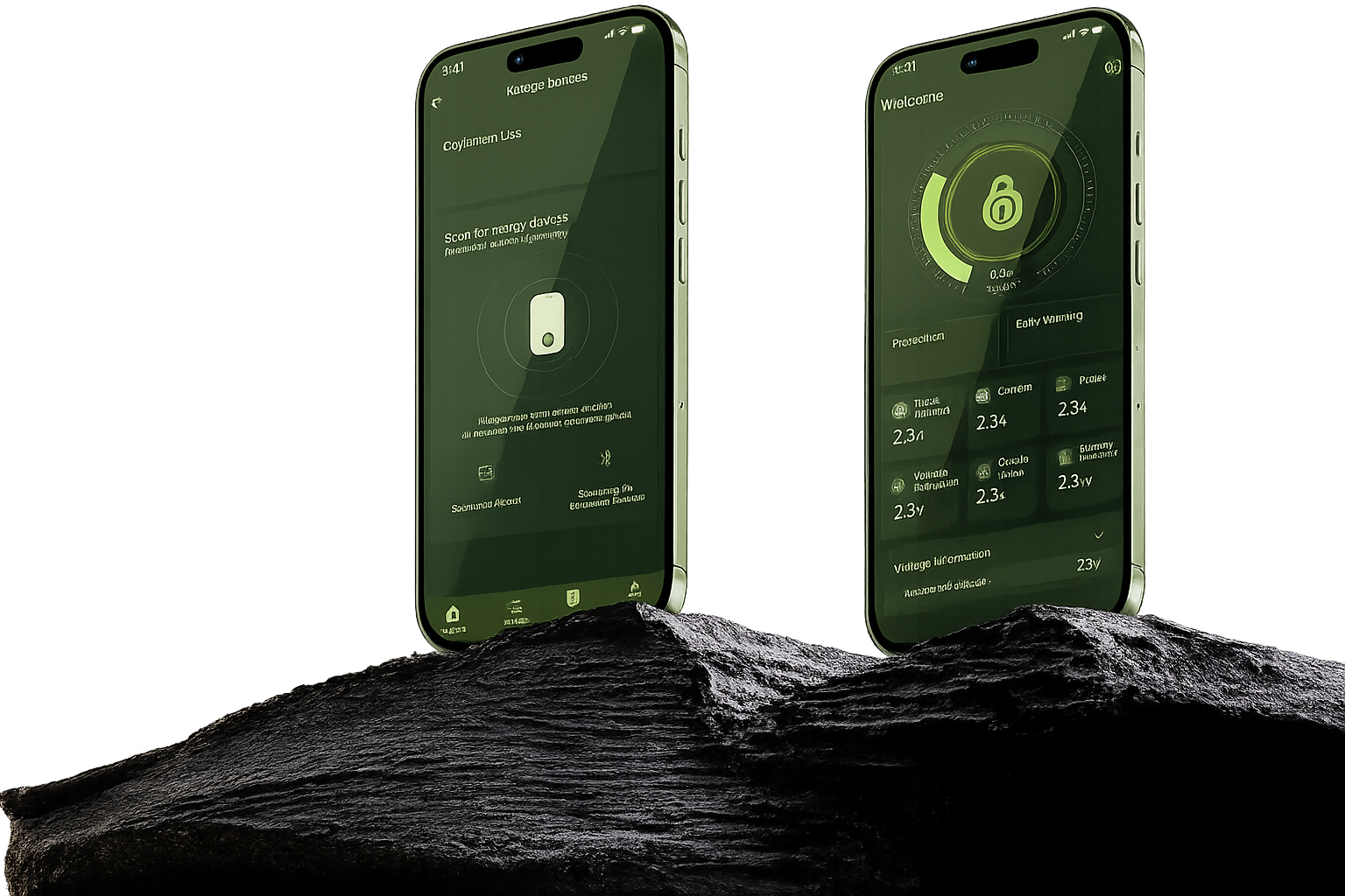
Smart APP control goes beyond parameter reading making life simpler by design.
Safety Always Takes Center Stage 5-Layer Security Shield,Ensure that everything is foolproof
More interfaces transform the battery from a single-device power source into an energy ecosystem hub.
High-performance protection board Featuring 800A maximum overcurrent capacity, dual-stage overcurrent protection, thermal protection, short-circuit prevention, energy management, and cell balancing—all in one robust protection solution.
Safety Always Takes Center Stage 5-Layer Security Shield,Ensure that everything is foolproof
Real-time telemetry from your phone.
DIGI App
IP67 sealed, overcharge & short-circuit protected.
Overcharge
Short-circuit
Over-temp
Under-volt
Over-current
Reverse
Real-time telemetry from your phone.
Battery Management System v4.
6,000+ cycles tested.
The Brand Story of DigiMarker's CS Series Battery Technology Breakthroughs
A deep understanding of user pain points is the starting point for DigiMarker's technological innovation. As the core of new energy power systems, battery stability directly determines product experience and safety. When the DigiMarker CS Series batteries faced two major issues—the burnout of the 12V DC-DC step-down module and damage to the vehicle controller during downhill travel with a fully charged battery—we formed a dedicated task force to tackle these industry challenges head-on. Through technological breakthroughs, we resolved user pain points and demonstrated our brand's commitment.
At the time, these two failures not only compromised user safety and brand reputation but also represented widespread industry challenges that most manufacturers could only address through reactive repairs or temporary workarounds. DigiMarker, however, insisted on addressing the root causes and took the lead in tackling these technical challenges.
The first hurdle was the burnout of the 12V DC-DC step-down module. Upon investigation, we found that in the original design, the module was directly connected to the battery circuit and remained constantly powered. On one hand, high-voltage spikes generated when the BMS cut off power during the final stages of charging would directly cause the module to fail; on the other hand, the module's 15mA static current draw would lead to battery damage due to over-discharge during prolonged winter storage.
The engineering team abandoned conventional protection approaches and started by restructuring the hardware topology. They connected the 12V DC-DC module's ACC control line to the BMS, allowing the BMS to centrally manage its on/off state. During charging, the BMS proactively shuts down the module, completely isolating it from high-voltage spikes; when not charging, the module activates only as needed, eliminating static leakage current and resolving both issues at their root.
Immediately afterward, a second major challenge emerged: during downhill braking with a fully charged battery, the massive regenerative current generated by the motor had nowhere to dissipate because the original BMS instantly cut off the charging MOSFET, resulting in high-voltage backflow that burned out the motor controller.
The team restructured the software logic and innovatively introduced a "regenerative current acceptance state," adding two custom parameters: Parameter 15 (discharge state determination delay threshold, default 5 seconds) and Parameter 14 (regenerative current acceptance threshold, default 3655 mV, higher than the standard overvoltage protection value), to reserve a buffer for the regenerative current.
The new logic establishes a comprehensive protection system: after the battery is fully charged, it enters a 5-second discharge delay assessment; upon meeting the criteria, it switches to the "feedback reception state." The BMS disables standard overvoltage protection and sets 3655 mV as the new threshold, allowing the battery cells to absorb the reverse voltage and protect the controller. If the voltage exceeds the threshold, the BMS shuts down the MOSFET and generates a 63 protection flag for easy maintenance.
From hardware redesign to software innovation, the DigiMarker R&D team has successfully overcome two major technical bottlenecks. This not only addresses users' core pain points but also enhances the stability and safety of the CS series batteries, breaking through industry-wide technical limitations and putting into practice the brand philosophy of "user-centric, technology-driven."
Technology knows no bounds, and our pursuit of excellence never ends. This breakthrough is merely a snapshot of DigiMarker's journey of innovation. In the future, we will continue to deepen our commitment to the new energy sector, listen to user needs, and use cutting-edge technology to solve industry challenges, creating more reliable battery products—breaking through barriers with technology and building trust through quality.
The Brand Story of DigiMarker’s CS Series Battery Technology Breakthroughs
A deep understanding of user pain points is the starting point for DigiMarker’s technological innovation. As the core of new energy power systems, battery stability directly determines product experience and safety. When the DigiMarker CS Series batteries faced two major issues—the burnout of the 12V DC-DC step-down module and damage to the vehicle controller during downhill travel with a fully charged battery—we formed a dedicated task force to tackle these industry challenges head-on. Through technological breakthroughs, we resolved user pain points and demonstrated our brand’s commitment.
At the time, these two failures not only compromised user safety and brand reputation but also represented widespread industry challenges that most manufacturers could only address through reactive repairs or temporary workarounds. DigiMarker, however, insisted on addressing the root causes and took the lead in tackling these technical challenges.
The first hurdle was the burnout of the 12V DC-DC step-down module. Upon investigation, we found that in the original design, the module was directly connected to the battery circuit and remained constantly powered. On one hand, high-voltage spikes generated when the BMS cut off power during the final stages of charging would directly cause the module to fail; on the other hand, the module’s 15mA static current draw would lead to battery damage due to over-discharge during prolonged winter storage.
The engineering team abandoned conventional protection approaches and started by restructuring the hardware topology. They connected the 12V DC-DC module’s ACC control line to the BMS, allowing the BMS to centrally manage its on/off state. During charging, the BMS proactively shuts down the module, completely isolating it from high-voltage spikes; when not charging, the module activates only as needed, eliminating static leakage current and resolving both issues at their root.
Immediately afterward, a second major challenge emerged: during downhill braking with a fully charged battery, the massive regenerative current generated by the motor had nowhere to dissipate because the original BMS instantly cut off the charging MOSFET, resulting in high-voltage backflow that burned out the motor controller.
The team restructured the software logic and innovatively introduced a “regenerative current acceptance state,” adding two custom parameters: Parameter 15 (discharge state determination delay threshold, default 5 seconds) and Parameter 14 (regenerative current acceptance threshold, default 3655 mV, higher than the standard overvoltage protection value), to reserve a buffer for the regenerative current.
The new logic establishes a comprehensive protection system: after the battery is fully charged, it enters a 5-second discharge delay assessment; upon meeting the criteria, it switches to the “feedback reception state.” The BMS disables standard overvoltage protection and sets 3655 mV as the new threshold, allowing the battery cells to absorb the reverse voltage and protect the controller. If the voltage exceeds the threshold, the BMS shuts down the MOSFET and generates a 63 protection flag for easy maintenance.
From hardware redesign to software innovation, the DigiMarker R&D team has successfully overcome two major technical bottlenecks. This not only addresses users’ core pain points but also enhances the stability and safety of the CS series batteries, breaking through industry-wide technical limitations and putting into practice the brand philosophy of “user-centric, technology-driven.”
Technology knows no bounds, and our pursuit of excellence never ends. This breakthrough is merely a snapshot of DigiMarker’s journey of innovation. In the future, we will continue to deepen our commitment to the new energy sector, listen to user needs, and use cutting-edge technology to solve industry challenges, creating more reliable battery products—breaking through barriers with technology and building trust through quality.
Extensive Battery Monitoring with Digimarker App
Download on the
Get it on
See how we change people’s lifestyles and make life simpler


Product launches, deep technical breakdowns and member-only deals.